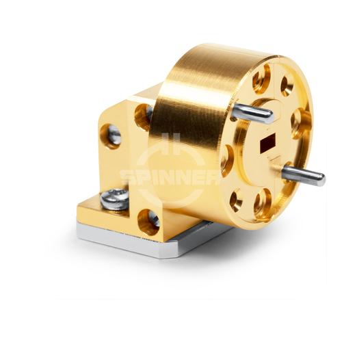
PCB launch connector R 740 (WR 12) 60-90 GHz thickness up to 2.2 mm product photo Front View L
For a larger view click on the picture.

PCB launch connector R 740 (WR 12) 60-90 GHz thickness up to 2.2 mm

533412C0001

RF characteristics

Number of interfaces:
2
Interface type:
R 740 per IEC 60153-3
Interface direction:
right angle
Waveguide interface:
precision split-block interface with anti-cocking rim
compatible with M3922/67-009 (UG-387/U-mod) type flanges
Frequency range:
60 to 90 GHz
Return loss:
12 dB

Mechanical characteristics

Installation type:
solderless
Inner conductor material / surface coating:
CuBe age hardened / gold-plated (PCB side)
Housing material / coating:
copper-alloy / gold-plated
Insulation material:
PEI
Weight, approx.:
50.0 g

Environmental conditions

Operating temperature:
-40 to +85 °C

Scope of delivery & accessories

Delivery scope:
protective cap

Further remarks

Remark:
PCB thickness: max. 2.2 mm
(permissible max. PCB thickness expandable with longer screws)
1):
PCB interface: transmission lines according to drawings below
Footnote:
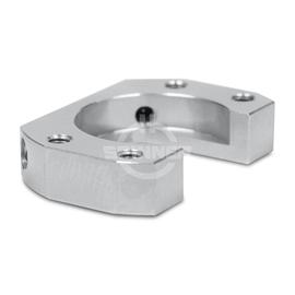
panel fixture BN: B25702
Customs tariff number:
85366930

Downloads

533412C0001-DS.pdf

Product data sheet – 533412C0001 – 533412C0001-DS.pdf

62424.pdf

PCB Layouts – 533412C0001 – PCB-Layouts for SPINNER EasyLaunch Connectors – 62424.pdf

A74932-0E.pdf

PCB Layouts – 533412C0001 – PCB-Layout coplanar RT/duroid 5880 LZ 0.254 mm – A74932-0E.pdf

A74933-0E.pdf

PCB Layouts – 533412C0001 – PCB-Layout coplanar RT/duroid 5880 0.254 mm – A74933-0E.pdf

A74934-0E.pdf

PCB Layouts – 533412C0001 – PCB-Layout microstrip RT/duroid 5880 0.254 mm – A74934-0E.pdf

A74935-0E.pdf

PCB Layouts – 533412C0001 – PCB-Layout microstrip RT/duroid 5880 LZ 0.254 mm – A74935-0E.pdf

A94270-0E.pdf

PCB Layouts – 533412C0001 – PCB-Layout microstrip RO3003 0.127 mm – A94270-0E.pdf

A94283-0E.pdf

PCB Layouts – 533412C0001 – PCB-Layout microstrip RO3003 0.254 mm – A94283-0E.pdf

A96165-0E.pdf

PCB Layouts – 533412C0001 – PCB-Layout coplanar RO3003 0.127 mm – A96165-0E.pdf

A96178-0E.pdf

PCB Layouts – 533412C0001 – PCB-Layout coplanar RT/duroid 5870 0.254 mm – A96178-0E.pdf

A96360-0E.pdf

PCB Layouts – 533412C0001 – PCB-Layout coplanar RT/duroid 5870 0.127 mm – A96360-0E.pdf

A99375-0E.pdf

PCB Layouts – 533412C0001 – PCB-Layout coplanar RO3003 0.254 mm – A99375-0E.pdf

D04825-0E.pdf

Drawing – 533412C0001 – Mechanical PCB-Design – D04825-0E.pdf

RoHS_Test&Measurement_10121583-TD.pdf

Technical document – 533412C0001 – RoHS-Certificate for Test & Measurement Components – RoHS_Test&Measurement_10121583-TD.pdf

M36456.pdf

Installation instructions – 533412C0001 – M36456.pdf