SPINNER Filters offer reliability, performance, and value
Radio Frequency (RF) filters are crucial components in mobile communication and broadcast networks. Their primary function is to selectively allow signals of certain frequencies to pass while blocking others, thereby managing interference and enhancing the clarity and quality of the transmission. Applications include cellular base stations, broadcasting, and other RF communication systems.
Critical Characteristics and Success Factors:
- Selectivity: The ability to precisely isolate specific frequency bands.
- Insertion Loss: Minimal loss of signal strength through the filter.
- Power Handling: Capability to manage the power level of the signal without degradation.
- Durability: Performance consistency over a range of environmental conditions.
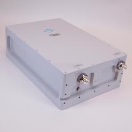
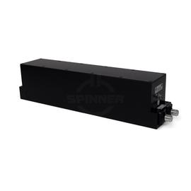
The Band-stop filter 900 MHz 200 W N female guarantees excellent, lossless mobile communication quality for use in in-building distributed antenna systems (DAS) or on mobile communication base stations outdoors.
Band-stop filtes are used to protect against specific interference by rejecting a particular frequency range while allowing all others to pass. Ideal in environments where specific frequency bands are known to cause disruption.
Outstanding RF characteristics, best possible passive intermodulation and VSWR
The Band-stop filter 900 MHz 200 W N female enables you to transmit high-frequency signals reliably and flawlessly with optimum protection of your sensitive equipment in a power range up to 200 W with maximum passive intermodulation (IM3) of -150 dBc.
The protection class is IP 65.
It supports the use of the following frequency bands : 900
The N-coaxial connectors were named after their inventor Paul Neill, who developed this standard for RF connectors in 1942. Often, however, the name also relates to the Navy Connector. Type N connectors can be used at frequencies up to 11 GHz, high-precision types up to 18 GHz. It is typically used in mobile communication applications with demanding mechanical and electrical requirements. SPINNER exclusively manufactures connectors with non-slotted outer conductor contacts and a special sealing profile in the connector head instead of the flat seal disk, specified by IEC or CECC. This ensures the most reliable sealing function.
Our RF filters are engineered with precision, offering exceptional selectivity and low insertion loss, which are critical for efficient RF communication. Our range includes filters designed for various specific applications, ensuring that whatever your needs, we have a filter that fits. With robust construction, our filters maintain performance across a broad range of environmental conditions, making them ideal for both mobile communication and broadcast networks.
Our unique approach to RF filter design combines innovative technology with practical application insights, resulting in products that not only meet but exceed industry standards. For anyone involved in the construction or operations of RF mobile communication or broadcast networks, our filters offer reliability, performance, and value.