SpinnerFlex®TopFit - ideal for signal transmission between base stations and antennas
SpinnerFlex®TopFit pre-fabricated coaxial cables (jumper cable assemblies) are the ideal solution for radio frequency signal transmission between base stations and antennas. They offer top-quality design, materials and manufacturing, ensuring optimal connectivity, easy installation, and fault-free functioning, even under extremely harsh environmental conditions.
A coaxial jumper cable assembly LF 1/2"-50-PE 7-16 female 4.3-10 male screw 9 m is a high quality low loss flexible corrugated cable of the size LF 1/2". It provides a reliable and stable transmission of radio frequency signals with very low attenuation in the frequency range DC to 3800 MHz, also on long distances. The cable is optimally shielded against interference, providing excellent, loss-free mobile communication quality for use in in-building distributed antenna systems (DAS) or in mobile communication base stations. In addition, a prefabricated coaxial jumper cable assembly LF 1/2"-50-PE 7-16 female 4.3-10 male screw 9 m is also suitable for a variety of demanding industrial applications or broadcast.
Outstanding IM characteristics with maximum passive intermodulation
A SPINNER coaxial jumper cable assembly LF 1/2"-50-PE 7-16 female 4.3-10 male screw 9 m guarantees outstanding IM characteristics with maximum passive intermodulation (IM3) of -156 dBc and low VSWR values over the entire frequency range and during the entire operating time of the cable. The robust construction defies even harsh outdoor conditions and for a temperature range from -55 to +85 °C. SPINNER coaxial cable assemblies comply with the RoHS 2002/95 Directive. The length of the cable is 9.0 m. The rugged coaxial cable has inner conductors made of copper, a PE dielectric insulation and a copper outer conductor. Inner and outer conductors are soldered 360° inductively. The degree of protection IP68 according to IEC 60529 is guaranteed.
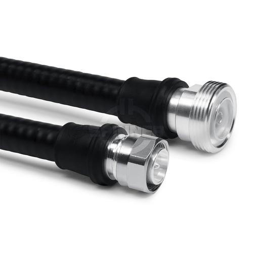
On one end there is a 7-16 female connector pre-assembled, on the other end there is a 4.3-10 male screw connector. Thus, you can use the cable as an adapter for the transition between 7-16 and 4.3-10 connector systems.
The 7-16 connector has become the most widely used coaxial connection system for mobile communication systems, due to its excellent mechanical and electrical properties. In order to achieve the industry leading intermodulation performance SPINNER applies silver-plating on all inner and outer conductor parts of the standard connector. As a supporting measure, we use exclusively non-magnetic materials, and we have minimized the number of RF contact points. The connection is especially suited for transmitting medium or high power indoors and outdoors.
The 4.3-10 connector system was designed to meet the latest requirements in mobile communication in terms of size, robustness, performance, and other parameters. Its small footprint supports the use of smaller components, mitigates risks if equipment is assembled without due care, and delivers outstanding electrical performance.
The screw connection, especially when mounted with a suitable torque wrench, provides the strongest hold and a constantly secure fit of the cable. In addition, the center slots in the contacts provide high contact pressure between the cable and the connector for optimum conductivity and signal strength.


