High-Performance Directional Couplers for radio frequency networks
A directional coupler is a passive component used in radio frequency (RF) systems to split or combine RF signals while maintaining the directional flow of the signal. Its primary function is to transfer a portion of the RF power flowing in one transmission line to another transmission line, typically with minimal loss.
Directional couplers operate based on the principle of electromagnetic coupling between transmission lines. They consist of at least four ports: the input port (usually called the main line), the output port (also known as the through port), and two auxiliary ports (the coupled port and the isolated port.
When an RF signal is applied to the input port, a portion of that signal is coupled to the coupled port while the majority of the signal continues through to the output port. The amount of power coupled to the auxiliary port is determined by the design of the directional coupler and is typically specified as a coupling factor in decibels (dB).
Directional couplers are essential components in broadcast stations or mobile communication networks. Couplers enable engineers to monitor signal strength, analyse performance, and distribute signals to various components within the broadcast or communication system. Use cases are:
- Signal Monitoring: Directional couplers allow RF engineers to monitor signal strength and quality at various points within the RF system, ensuring optimal performance.
- Signal Measurement: They facilitate accurate measurement of RF signals for troubleshooting, maintenance, and performance optimization.
- Signal Distribution: Directional couplers enable the distribution of RF signals to multiple components or devices within the transmission line without significant signal loss.
- Isolation: They provide isolation between the input and output ports, minimizing interference and ensuring signal integrity.
- Versatility: SPINNER directional couplers are available in various designs and frequency ranges, making them suitable for a wide range of broadcast or mobile communication system applications.
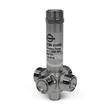
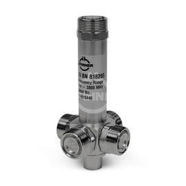
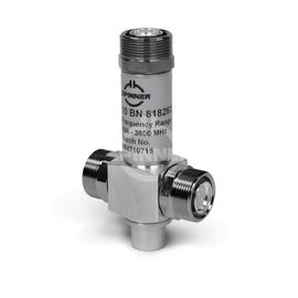
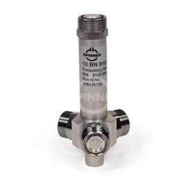
The Coaxial directional coupler 3 dB X-Style 300 W 694-2700 MHz 4.3-10 female guarantees excellent, lossless mobile communication quality for use in in-building distributed antenna systems (DAS) or on mobile communication base stations outdoors.
SPINNER directional couplers are characterized by highly effective signal isolation and extremely low intermodulation (low PIM).
Our Coaxial directional coupler 3 dB X-Style 300 W 694-2700 MHz 4.3-10 female is meticulously engineered to meet the demanding requirements of high performance RF systems. Designed and built with precision and versatility in mind, these directional couplers offer unparalleled performance for RF engineers building full broadcast systems or install mobile communication networks.
Key Features:
- Accurate signal monitoring and measurement capabilities
- High-quality construction for long-term reliability
- Wide frequency range to accommodate diverse broadcast or mobile communication system needs
- Excellent signal isolation to minimize interference
- Easy integration into existing broadcast or mobile communication setups
- Robust design suitable for demanding broadcast or mobile communication environments
Outstanding RF characteristics, best possible passive intermodulation and VSWR
The Coaxial directional coupler 3 dB X-Style 300 W 694-2700 MHz 4.3-10 female enables you to transmit high-frequency signals reliably and flawlessly with optimum protection of your sensitive equipment in a power range up to 300 W (per port) with maximum passive intermodulation (IM3) of -155 dBc.
The protection class is IP 65.
It supports the use following frequency bands : 700, 800, 900, 1500, 1800, 2100, 2300, 2400, 2600
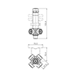
The 4.3-10 connector system was designed to meet the latest requirements in mobile communication in terms of size, robustness, performance, and other parameters. Its small footprint supports the use of smaller components, mitigates risks if equipment is assembled without due care, and delivers outstanding electrical performance.
The terms 'H-style' and 'X-style' directional couplers refer to different configurations or layouts of directional couplers based on the physical arrangement of their internal components.
- X-style directional couplers have a diagonal or crisscross layout, resembling the letter 'X' in their configuration.
- In X-style couplers, the coupled and isolated ports are typically arranged diagonally across the mainline, intersecting at a central point.
- X-style couplers are known for their compact design and efficient use of space, making them suitable for applications where size and footprint are critical considerations.
In terms of functionality and performance, both H-style and X-style directional couplers operate on the same principles of electromagnetic coupling and signal separation. The choice between the two styles often depends on factors such as available space, installation requirements, and system design preferences. Each style offers advantages in certain scenarios, and engineers may select the most appropriate style based on the specific needs of their RF system.
Invest in our high-performance directional couplers to elevate the performance and reliability of your broadcast or mobile communication system. Trust in our expertise and commitment to delivering superior RF components for your broadcasting needs. Overall, this directional coupler offers a simple and cost-effective solution for your installation.